UPGW WIFI、5G 共部署场景本地分流测试
测试内容
测试多
upstream,多downstream,多lbp情况下的分流功能
测试拓扑
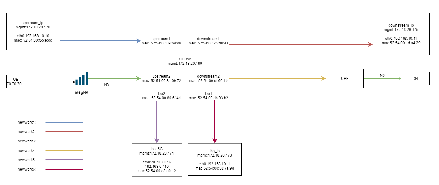
UPGW 接入两个 upstream:upstream1、upstream2
两个 downstream:downstream1、downstream2
两个 lbp:lbp1、lbp2
并且各个接口均网络隔离
UPGW 配置
upstream1对应PORT0downstream1对应PORT1lbp_ip对应PORT2upstream2对应PORT3downstream2对应PORT4lbp_5G对应PORT5
[root@NES ~]# cat /var/lib/appliance/nts/nts.cfg
[PORT0]
name = UP
description = 82540EM Gigabit Ethernet Controller
pci-address = 0000:00:0d.0
traffic-type = mixed
traffic-direction = upstream
egress-port = 1

[PORT1]
name = DOWM
description = 82540EM Gigabit Ethernet Controller
pci-address = 0000:00:0e.0
traffic-type = mixed
traffic-direction = downstream
egress-port = 0

[PORT2]
name = 0000:00:0f.0
description = 82540EM Gigabit Ethernet Controller
pci-address = 0000:00:0f.0
traffic-type = mixed
traffic-direction = lbp
egress-port = 0
lbp-mac = 52:54:00:58:7a:9d

[PORT3]
name = UP
description = 82540EM Gigabit Ethernet Controller
pci-address = 0000:00:0a.0
traffic-type = mixed
traffic-direction = upstream
egress-port = 4

[PORT4]
name = DOWM
description = 82540EM Gigabit Ethernet Controller
pci-address = 0000:00:0b.0
traffic-type = mixed
traffic-direction = downstream
egress-port = 3

[PORT5]
name = 0000:00:10.0
description = 82540EM Gigabit Ethernet Controller
pci-address = 0000:00:10.0
traffic-type = mixed
traffic-direction = lbp
egress-port = 3
lbp-mac = 52:54:00:e8:a0:12

[VM common]
max = 32
number = 2
vhost-dev = /var/lib/appliance/nts/qemu/usvhost-1

[NES_SERVER]
ctrl_ip = 0.0.0.0
ctrl_port = 9515

[REDIS_SERVER]
host=127.0.0.1
port=6379

[KNI]
max = 32
测试内容及步骤
1、upstream 到 downstream 直通
upstream_ip -> 192.168.10.11: 192.168.10.10 ping 192.168.10.11
测试
upstream1可以直通到downstream1,分别在upstream_ip,downstream_ip侧抓包,报文被正常透传。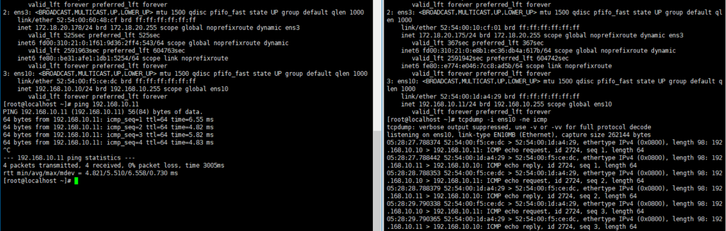
UE ->192.168.6.110: gtpu 报文 , ue_ip :70.70.70.1 ping 192.168.6.110
测试
upstream2可以直通到downstream2,在N6侧抓包,报文被正常透传。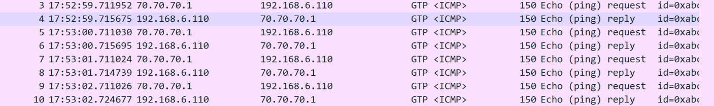
2、分流功能
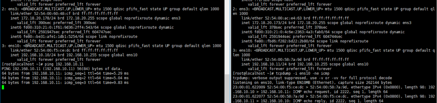
upstream_ip ->192.168.10.11 : 192.168.10.10 ping 192.168.10.11
测试步骤1、配置分流规则前,
192.168.10.10ping 通192.168.10.11,分别在upstream_ip,downstream_ip侧抓包,报文被正常透传。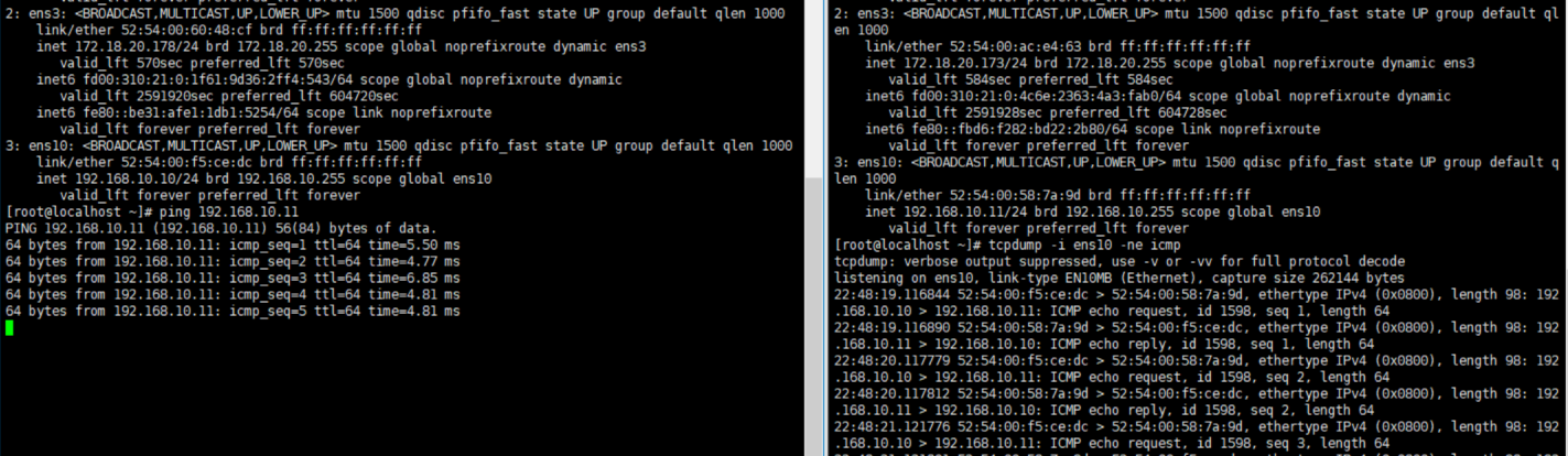
测试步骤2、配置分流规则后,
192.168.10.10可以 ping 通192.168.10.11,分别在upstream_ip,lbp_ip侧抓包,报文被正常分流至lbp_ip,并且UPGW正常回复了lbp_ip的arp应答。在
lbp_ip侧可以抓到正常的arp应答报文。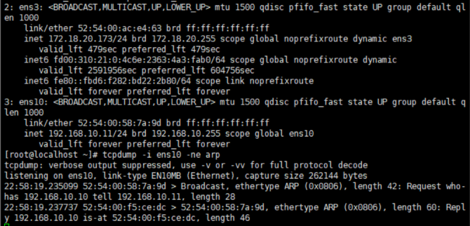
# 分流规则
route add 52:54:00:58:7a:9d ace4d210-3d92-422b-83d7-11a0de50fea8 prio:98,srv_ip:192.168.10.12/32,encap_proto:noencap,dst_lbp_port:2
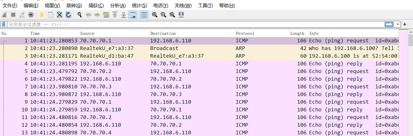
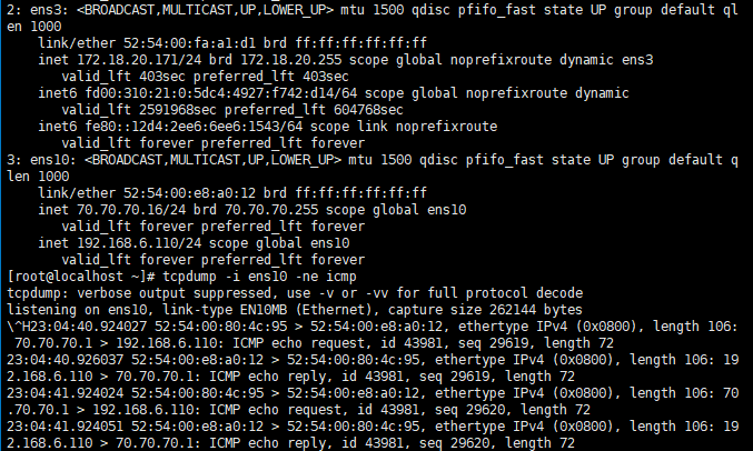
UE -> 192.168.6.110:
gtpu报文, ue_ip: 70.70.70.1 ping 192.168.6.110测试步骤1、配置分流规则前,
ue_ip: 70.70.70.1ping通192.168.6.110,在N6侧抓包,报文被正常透传。
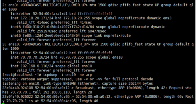
配置分流规则后,ue_ip: 70.70.70.1 ping通 192.168.6.110,在 N6 侧未抓到报文,在 lbp_5G 侧抓到报文,说明报文被正常分流至 lbp_5G,并且 UPGW 正常回复了 lbp_5G 的 arp 应答。
在 lbp_5G 侧可以抓到正常的 arp 应答报文。
# 分流规则
route add 52:54:00:e8:a0:12 ace4d210-3d92-422b-83d7-11a0de50fea5 prio:98,srv_ip:192.168.6.110/32,encap_proto:gtpu,dst_lbp_port:5
在 N6 侧未抓到报文
在 lbp_ 5G 侧抓到报文
注:测试时,两者分流测试是同时进行的
测试结论
UPGW 此次提交修改可以满足,UPGW 多 upstream,downstream,多 lbp 的组网场景。
http://review.sh.99cloud.net/#/c/33763/